-1791966549842.webp)





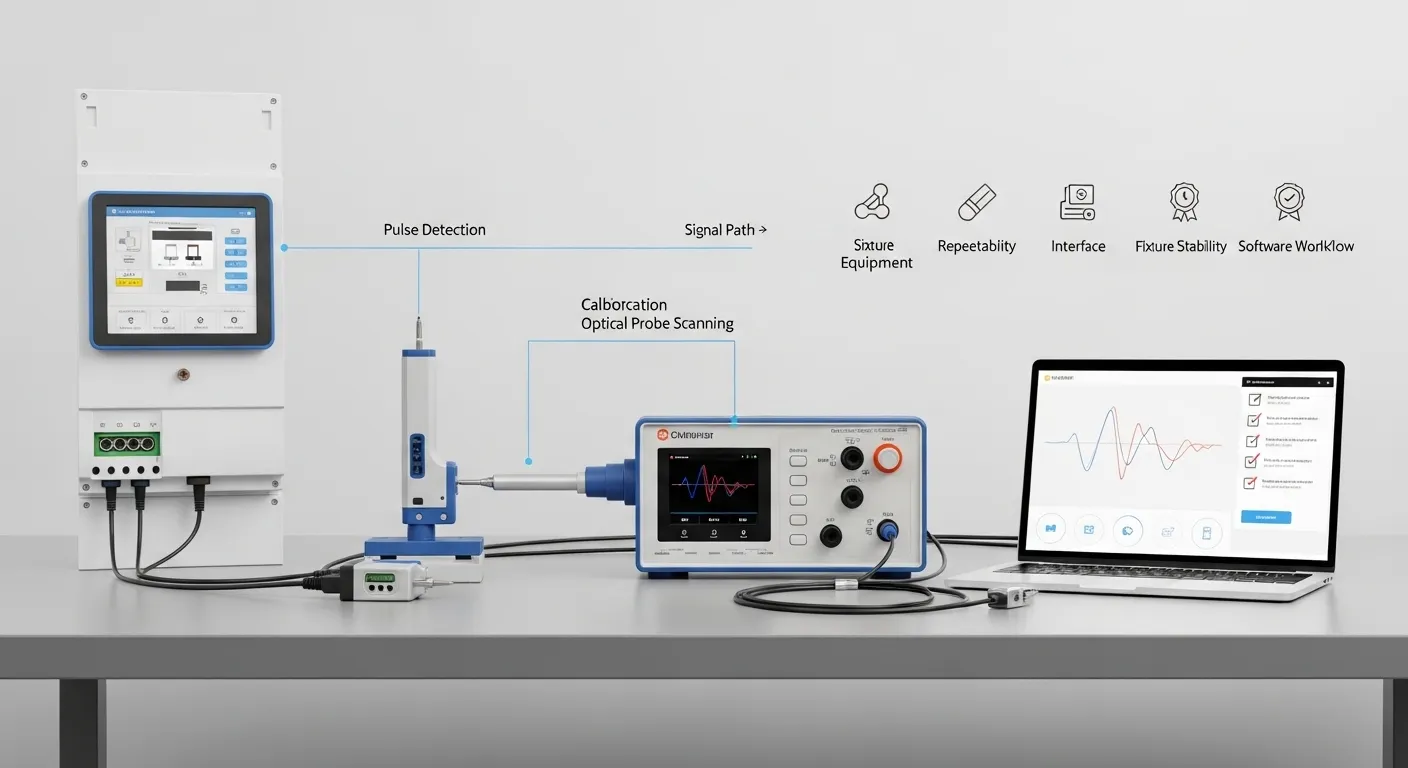

Tespro provides metering optical probes and meter testing support solutions for QA labs, meter manufacturers, utilities, metrology teams, and field calibration engineers. When selecting a calibration optical probe, buyers should confirm pulse detection needs, meter standard, interface type, fixture stability, software compatibility, and calibration workflow before requesting a quote.
For meter testing applications, the main risk is not only whether the probe can “see” the meter. The real issue is whether it can detect pulses repeatably, transfer a clean signal to the calibration system, and fit the physical setup of the meter under test.
This checklist helps technical and procurement teams prepare specifications for a calibration probe for optical measurement, optical pulse pickup, or photoelectric scanning head used in lab and field meter testing workflows.
When a Calibration Optical Probe Is Needed
A calibration optical probe is used when meter pulses, LED flashes, infrared outputs, or mechanical disc marks need to be detected during meter verification or accuracy testing. It may connect to a meter test bench, portable calibrator, reference standard, PC software, or other test equipment.
Buyers usually need this type of probe for:
- Electricity meter calibration and verification
- Meter factory QA testing
- Utility field inspection
- Meter test stand operation
- Reference meter comparison
- Mechanical disc meter testing
- Electronic meter LED pulse detection
- Lab acceptance testing before batch procurement
A normal meter reading optical probe may be designed mainly for local communication, data reading, or configuration. A calibration optical probe must be evaluated more carefully for pulse detection stability, output signal compatibility, and repeatable positioning.
For broader optical probe buying criteria, buyers can also review Tespro’s related guide: Energy Meter Optical Probe Purchase Checklist.
Accuracy Risk Starts With Pulse Detection
In a calibration workflow, the probe becomes part of the measurement chain. If the optical probe misses pulses, triggers falsely, shifts position, or sends an unstable output signal, the test result can become unreliable.
Before purchase, QA managers should confirm:
- Meter pulse type
- LED color or infrared pulse behavior
- Mechanical disc mark detection needs
- Pulse width and pulse frequency range
- Sensitivity to weak pulses
- Ambient light resistance
- Output voltage or signal type
- Sampling distance and alignment method
- Fixture stability during repeated tests
This is why calibration probe selection should not be based only on connector type or price. The probe must match the meter, the test equipment, and the operating environment.
Calibration Probe vs Meter Reading Optical Probe
A meter reading optical probe is commonly used to communicate with a meter through an optical port. It may support local reading, programming, configuration, diagnostics, or firmware-related workflows depending on the meter and software.
A calibration optical probe or photoelectric scanning head is usually selected for a different job. It detects pulse output, disc rotation, or LED flashing so the calibration device can compare meter output against a reference.
The buyer should clarify the required function before requesting a quotation:
- Communication probe: Used for meter reading or configuration through an optical port.
- Pulse sensing probe: Used to detect LED or infrared pulses for calibration.
- Scanning head: Used for mechanical disc marks, LED pulses, or meter test bench workflows.
- Hybrid requirement: Some projects may need communication and pulse detection in related workflows, but each function should be specified clearly.
If IEC 62056-21 communication is part of the project, check the interface and software requirements carefully. For more detail, visit Tespro’s IEC 62056 Optical Probe Compliance Buyer Guide.
Key Specifications Buyers Should Confirm
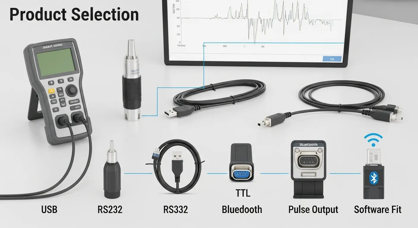
A calibration optical probe should be reviewed as a technical component, not only as an accessory. The following specification areas affect product selection and quotation accuracy.
Optical and Pulse Detection Details
Confirm whether the probe must detect visible LED pulses, infrared pulses, or mechanical disc marks. Also confirm whether the meter outputs active energy pulses, reactive energy pulses, or both.
Important details include:
- LED pulse type
- Infrared or visible light detection
- Mechanical disc mark detection
- Pulse width
- Pulse frequency or expected test speed
- Weak pulse detection needs
- Meter constant
- Ambient light exposure
- Sampling distance from meter surface
Interface and Output Signal
The probe must match the receiving device. A probe that fits the meter but does not match the test bench input can still fail procurement acceptance.
Common interface or output points to confirm include:
- USB connection for PC-based workflows
- RS232 or serial connection for legacy systems
- TTL or pulse output for test benches
- Bluetooth for specific field workflows
- Output voltage level
- Cable length
- Connector type
- Driver or operating system support
- Software compatibility
For PC-based meter reading or communication requirements, buyers can compare interface factors in Tespro’s USB Optical Probe Meter Reading Buyer Checklist. For wireless field workflows, see the Bluetooth Optical Probe Field Team Buying Checklist.
Fixture Stability and Repeatability
Probe positioning is often overlooked during procurement. In real testing, alignment can affect repeatability as much as electronic specifications.
A stable fixture helps the probe stay aligned with the LED window, infrared output, or disc mark during repeated tests. This is especially important for batch testing, field verification, and meters with recessed or angled optical areas.
Common fixture options include:
- Magnetic attachment
- Suction cup mounting
- Telescopic bracket
- Flexible rack
- Custom holder
- Cable strain relief
- Test bench fixture integration
The right option depends on the meter face, housing material, pulse position, test bench layout, and whether the same probe must support multiple meter models.
Standards and Compatibility Checks
Standards help narrow the selection, but they do not replace a full compatibility review. Buyers should confirm both the meter communication standard and the calibration pulse detection requirement.
Relevant standards or protocol areas may include:
- IEC 62056-21 for optical meter communication
- IEC 62053-31 for pulse output considerations
- ANSI C12.10 where applicable
- DLMS/COSEM if data communication is involved
- Local utility or lab acceptance requirements
Do not assume that one standard automatically confirms all calibration functions. A meter may support optical communication, while the calibration workflow still requires a specific pulse pickup output, fixture, software setting, or test bench input.
Calibration Optical Probe RFQ and Acceptance Checklist
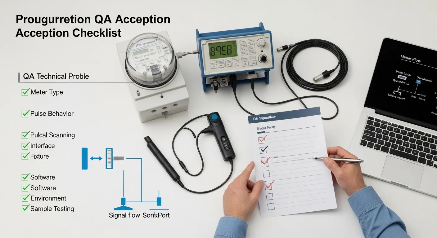
Use this checklist before requesting a datasheet, sample, or quotation from Tespro.
| Requirement area | What to confirm | Why it matters | RFQ detail to send |
|---|---|---|---|
| Meter type | Mechanical disc, electronic LED, smart meter optical port | Defines detection method | Meter model and meter type |
| Pulse behavior | LED, infrared, active/reactive pulse, disc mark | Prevents missed or false pulses | Pulse type and meter constant |
| Interface | USB, RS232, TTL, Bluetooth, custom connector | Must match test equipment | Required port and output signal |
| Software | Test bench software, PC software, driver, OS | Avoids integration failure | Software name or workflow |
| Fixture | Magnet, suction cup, bracket, rack, custom holder | Supports repeatable alignment | Meter face photo or drawing |
| Environment | Lab, factory, field, ambient light, temperature | Affects durability and detection | Operating conditions |
| Quantity and sample | Trial sample or batch order | Supports procurement approval | Quantity and sample need |
This table can also be used as an internal QA acceptance checklist. Before bulk ordering, test the probe with actual meter models, real software, and the target calibration equipment.
Software and Calibration Workflow Fit
A calibration probe should fit the complete test process. The buyer should map the signal path before ordering.
A typical workflow may include:
- Meter generates LED, infrared, or disc movement signal.
- Probe detects the optical event.
- Probe sends pulse or communication signal to the calibration system.
- Reference standard or test bench compares output.
- Software records the result and produces the report.
If any part of this chain is unclear, procurement risk increases. Buyers should confirm whether the probe is used for manual tests, automated meter test stands, portable field calibration, or factory QA stations.
Common Procurement Mistakes to Avoid
Many issues appear after delivery because the RFQ was too general. Avoid asking only for “an optical probe for meter calibration” without technical context.
Common mistakes include:
- Choosing a communication probe when pulse detection is needed
- Ignoring output voltage or signal format
- Forgetting driver or software compatibility
- Assuming one fixture fits all meter housings
- Not checking weak LED pulse behavior
- Not testing under real ambient light conditions
- Missing cable length or connector requirements
- Skipping sample validation before larger orders
For QA labs, the safest approach is to request a compatibility review with actual meter and test equipment details.
What to Send Tespro for a Quote
To help Tespro recommend the right configuration, send clear technical and commercial details with your inquiry.
Include:
- Required product type
- Quantity
- Application: lab, field, factory QA, utility inspection, or test bench
- Meter model and meter type
- Meter standard or protocol
- Pulse type and meter constant if known
- Required interface or output signal
- Test bench, calibrator, or reference standard model
- PC software, driver, or operating system needs
- Cable length and connector requirements
- Fixture preference or meter face constraints
- Operating environment
- Accuracy or repeatability requirements
- Datasheet, sample, demo, or consultation needs
- Delivery destination
- Any drawing, site photo, system diagram, or written specification
The more complete the RFQ, the easier it is to avoid wrong configuration, repeated clarification, and delayed approval.
Why Work With Tespro
Tespro supports industrial metering, smart meter communication, optical probe selection, meter testing equipment, calibrators, data transmission units, industrial routers, gateways, and software platform workflows.
For calibration probe projects, our role is to help buyers connect the device requirement with the real application. That may include lab testing, meter factory QA, field verification, or broader AMI/AMR and utility metering projects.
Instead of selecting only by product name, buyers can share the meter, interface, fixture, and workflow details. Tespro can then help review the requirement and guide the buyer toward a suitable optical probe or related metering solution.
Frequently Asked Questions
What is the difference between a calibration optical probe and a meter reading optical probe?
A meter reading optical probe is mainly used for local meter communication. A calibration optical probe or scanning head is used to detect pulses, LED flashes, infrared output, or disc movement during meter accuracy testing.
Which specs affect calibration repeatability?
Pulse type, wavelength range, pulse width, output signal, sampling distance, fixture stability, and ambient light resistance can affect repeatability. Buyers should test the probe with real meters and actual calibration equipment before bulk orders.
Should we choose USB, RS232, TTL, or Bluetooth?
Choose the interface based on the receiving device. USB may fit PC software, RS232 may fit serial systems, TTL may fit pulse inputs, and Bluetooth may suit field workflows. Confirm software and driver support before ordering.
Can one probe support both mechanical and electronic meters?
It depends on the probe design and meter types. Some workflows require disc mark detection, while others need LED or infrared pulse detection. Send meter model details before assuming one probe can support all test cases.
Does IEC 62056-21 compatibility confirm calibration compatibility?
Not always. IEC 62056-21 relates to optical meter communication. Calibration workflows may also need pulse detection, output signal matching, stable fixture placement, and software or test bench compatibility.
When should buyers request a sample?
Request a sample when the meter type, pulse signal, fixture, software, or test bench compatibility is uncertain. Sample testing helps QA teams confirm repeatability before larger procurement.
Request a Calibration Optical Probe Quote From Tespro
Share your meter model, calibration workflow, interface requirement, pulse type, fixture constraints, software needs, quantity, and delivery destination with Tespro. Our team can review your application and help you request the right calibration optical probe datasheet, sample, quotation, or technical consultation for your meter testing project.