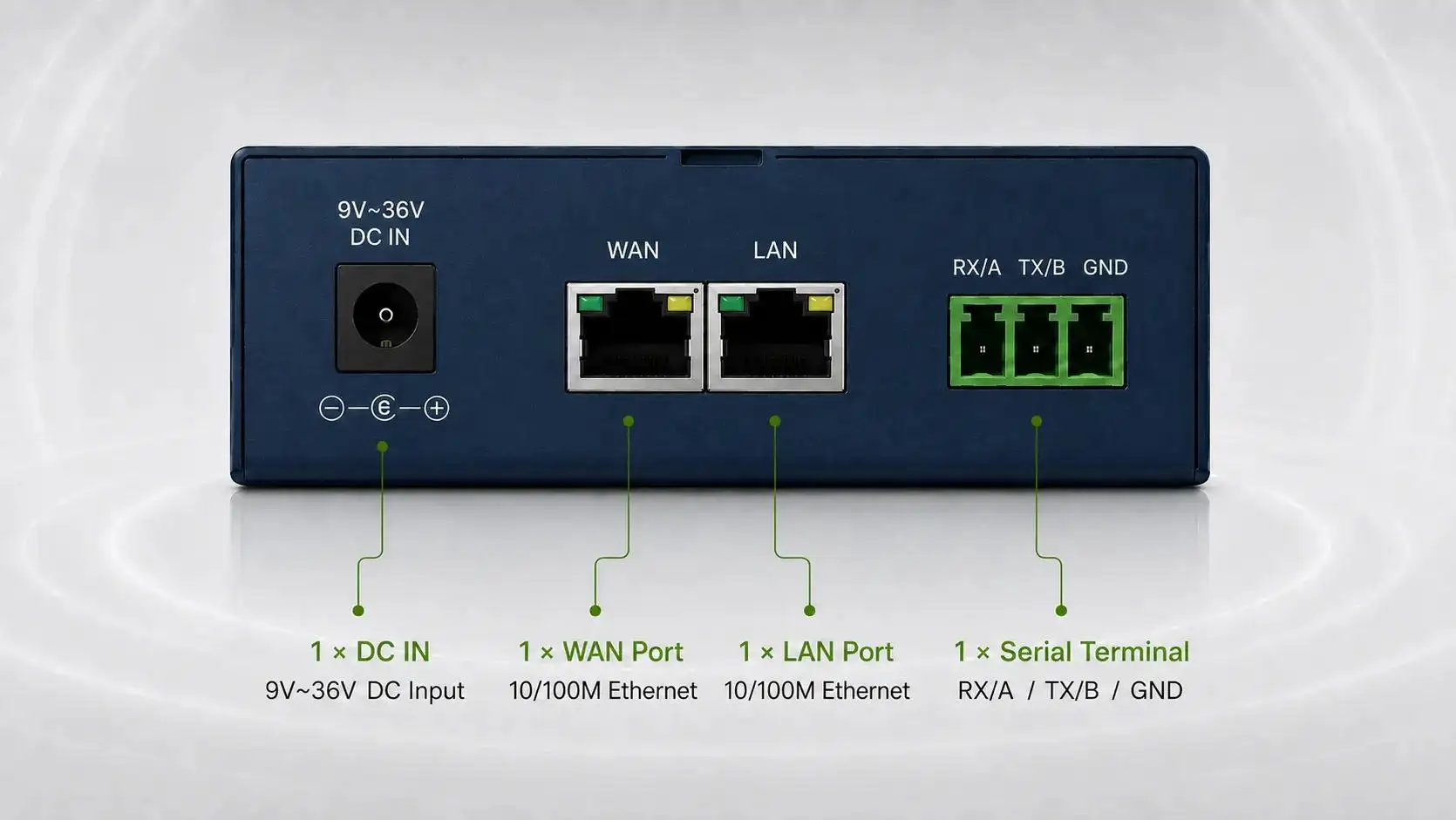
-1791966549842.webp)





Accuracy testing of utility metering used to require multiple expensive tools. This was due to the way mechanical meters and electrical meters operate. Mechanical utility meters have a rotating disc whereas electrical meters work with light pulses. The currently available Optical Sensor Calibration Probes address this issue by combining two sensing capabilities into one unit. The TP-17C Dual-Function Scanning Probe by Tespro is used as an example to present the nature and the science of light detection and pulse conversion.
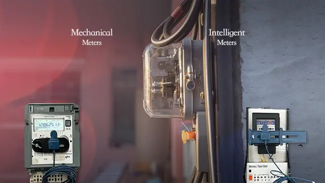
The First Problem: The Existence of Two Meter Types with Different Signals
Electric and mechanical meters do not represent the same physical magnitude. To understand the design of the dual-function probe, it is essential to understand the difference in the way mechanical and electrical meters operate.
• Mechanical Meters (Induction Disc Meters): The operation of these meters is based on an aluminum disc, which is set into motion through an Eddy current. The disc has either painted or marked sections and therefore reflects light. The probe in this case is used to determine if the light is reflected or not.
• Electrical Meters (Static/Smart Meters): These meters come with a front panel that has an LED which blinks in a manner proportional to the amount of energy consumed (for example 1000 imp/kWh). The probe must detect short, repetitive light pulses – typically red or infrared (IR).
• Traditional approach: Technicians carried one reflective optical sensor for mechanical meters and a separate photodiode-based pulse pickup for electronic meters. Switching between them was time-consuming and error-prone.
• The dual-function breakthrough: A single Optical Sensor Calibration Probe like the TP-17C houses both sensing elements and adds a mode-switching mechanism, eliminating the need for two tools.
Dual-Sensing System: How One Probe Reads Both Worlds
The core of any dual-function calibration probe is its optoelectronic front end. The TP-17C uses a hybrid design that can work with both reflected light (from a mechanical disc mark) and emitted light (from an electric meter's LED).
• For mechanical meters (reflective mode): The probe contains an infrared LED that illuminates the disc surface. A phototransistor or photodiode measures the reflected intensity. When the black mark passes, reflected light drops sharply – generating a "disc revolution" event.
• For electric meters (pulse mode): The same photodetector listens for external light pulses from the meter's optical port. The internal circuitry is tuned to reject continuous ambient light while capturing pulses as short as 200 ms (minimum pulse width).
• A shared optical path: Both modes use the same lens and window, but the firmware changes the gain, filtering, and reference thresholds. This ensures neither false triggers nor missed counts.
• Tespro's implementation: The TP-17C achieves this with a silicon chip that supports multiple supply voltages (5V, 12V, 24V DC) and automatically adapts to different connector types – a sign of careful signal integrity design.
The Role of Wavelength and Light Type: Infrared vs. Visible Red
Different meter types emit or reflect light at different wavelengths. A universal probe must respond to both IR and visible red without saturation or blind spots.
• Mechanical meter marks: Often printed with black ink that absorbs near-IR (850–940 nm). The probe's IR LED works at these wavelengths, while ambient visible light is optically filtered out.
• Electric meter LEDs: Typically deep red (630–660 nm) or sometimes infrared (for smart meter optical ports). The TP-17C's photodetector has a broad spectral sensitivity from 400 nm to 1100 nm, covering both.
• Why wavelength matters: Using the wrong wavelength leads to poor contrast (mechanical) or missed pulses (electric). A dual-function probe must have a flat spectral response or switchable optical filters.
• Tespro's "Strong Compatibility" feature: According to the datasheet, the TP-17C picks up visible and infrared light of different colors and wavelengths, then converts them into electric pulses – exactly this spectral agility.
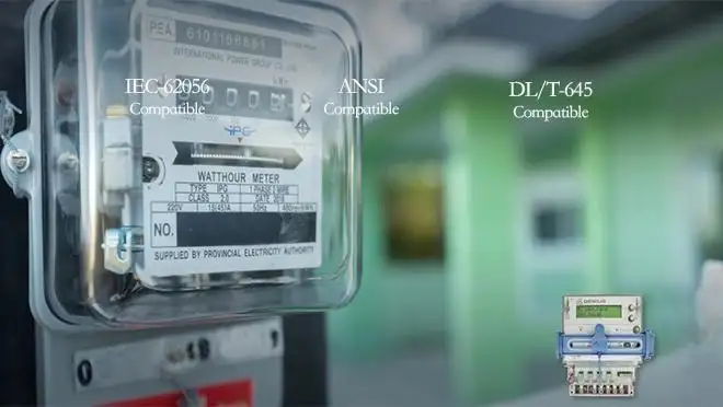
Signal Conditioning and Internal Algorithm: From Raw Light to Clean Pulses
Raw photocurrent is noisy. The probe must shape it into a clean, logic-level square wave that a calibrator or counter can understand.
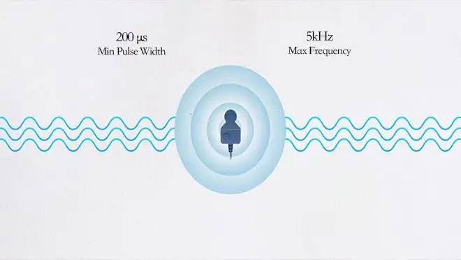
• Amplification and thresholding: A transimpedance amplifier converts photocurrent to voltage. An adjustable comparator compares this voltage against a dynamic threshold. The TP-17C has a maximum detectable pulse frequency of 5 kHz – fast enough for high-precision electronic meters.
• Debouncing and hysteresis: Mechanical disc vibrations can cause multiple edges per revolution. The probe's algorithm applies a minimum off-time (200 ms maximum pulse width) to debounce the signal.
• Light interference rejection: Ambient light (sunlight, fluorescent lamps) introduces a DC offset. The TP-17C uses AC coupling or synchronous detection to suppress it, allowing reliable operation both indoors and outdoors.
• Internal algorithm in TP-17C: The case study mentions that "various input signals are run through an advanced internal algorithm and transformed into a regular and dependable electric impulsion." This ensures consistent data capture across meter types.
One-Button Mode Switching and Visual Feedback (LED Indicators)
A dual-function probe is useless if switching modes is complicated. The TP-17C employs a simple button-press mechanism with clear color-coded status.
• Button-down for mechanical mode: The LED turns red. The probe enables its internal IR emitter and sets the detector for reflective operation. The output pulse corresponds to one disc revolution.
• Button-up for electric mode: The LED turns blue. The IR emitter is turned off, and the probe now works as a passive pulse receiver. The output pulse follows the meter's LED flash.
• Why visual feedback matters: Technicians working on a live panel cannot second-guess which mode is active. Red/blue LEDs provide an immediate, eyes-free confirmation.
• Integration with TP-GS bracket: The TP-17C is designed to be used with TP-GS2 or TP-GS3 magnetic brackets. This mechanical interface holds the probe at the correct distance and angle – critical for repeatable optical coupling.
Practical Advantages in the Field: The TP-17C as an Example
The real value of a dual-function Optical Sensor Calibration Probe appears during site work, especially when a utility has mixed meter inventories.
• One tool, all meters: No more swapping between a reflective pickup and a pulse probe. The TP-17C covers both, reducing the number of items in a test kit.
• Faster on-site verification: A case study from Tespro shows that a utility testing company cut equipment transport volume and reduced calibration time by using the TP-17C. One-button switching eliminated the need to reconfigure wiring or change sensors.
• Works in harsh environments: With an operating temperature range of -40°C to +70°C and IP54 rating (dust-resistant and splash-proof), the probe can be used in substations, outdoor meter boxes, and industrial plants.
• Low power and flexible supply: Default 5V DC (≤40 mA) is suitable for most calibrators. The optional 12–36V DC input allows direct connection to PLC or battery systems without an extra power converter.
Environmental Durability and Compatibility
A calibration probe must survive daily field use. Tespro has designed the TP-17C with robust mechanical and electrical parameters.
• Cable and connector: Standard 3-meter cable (2 m optional) with bare wires or customizable connector. This allows the probe to be integrated into existing test benches or handheld calibrators.
• Enclosure material: PC (polycarbonate) body plus ABS+PC hybrid. The weight is only 50 grams, reducing strain on the meter's optical port or bracket.
• IP54 protection: Protected against limited dust ingress and water splashes from any direction. Not submersible, but more than adequate for rain or condensation.
• Mounting flexibility: The TP-GS2 magnetic fixture holds the probe onto any ferrous meter housing. For non-magnetic surfaces, adhesive brackets or strap-on adapters can be used.
Conclusion
The ability of an Optical Sensor Calibration Probe to work with both mechanical and electric meters is not magic – it is the result of thoughtful optoelectronic design: a dual-wavelength photodetector, switchable illumination, adaptive signal conditioning, and a straightforward user interface.
Tespro's TP-17C exemplifies these principles with its one-button mode switching, wide temperature tolerance, and high sensitivity (5 kHz / 200 ms). For utilities, test labs, and field service teams, such a probe simplifies inventory, speeds up accuracy tests, and reduces human error. As the energy grid continues to mix old electromechanical meters with new smart meters, dual-function calibration probes will become the standard – not the exception.
FAQs
Q1: Does the TP-17C require external power from a wall outlet?
A: No, it operates on DC 5V (default) or optional 12–36V, suitable for portable calibrators or field terminals.
Q2: What is the probe's maximum detectable pulse frequency?
A: This device logs a maximum registering rate of 5 kHz. Most advanced electronic meters rate higher as many of them have LEDs that blink in a faster rate, so this device can likely be used with most advanced electronic meters.
Q3: Can the probe be used outside in the sun?
A: Yes, the TP-17C reduces light interference, so it works well inside and outside.
Q4: Is the TP-17C a good smart meter option with an IR optical port?
A: Certainly. The TP-17C covers a broad spectral range that includes the visible red and infrared.
Q5: I want to know how to tell which of the two modes (mechanical or electric) the probe is in?A: The LED shows the mode, with red for mechanical and blue for electric. The modes are changed by single press of the button.