-1791966549842.webp)





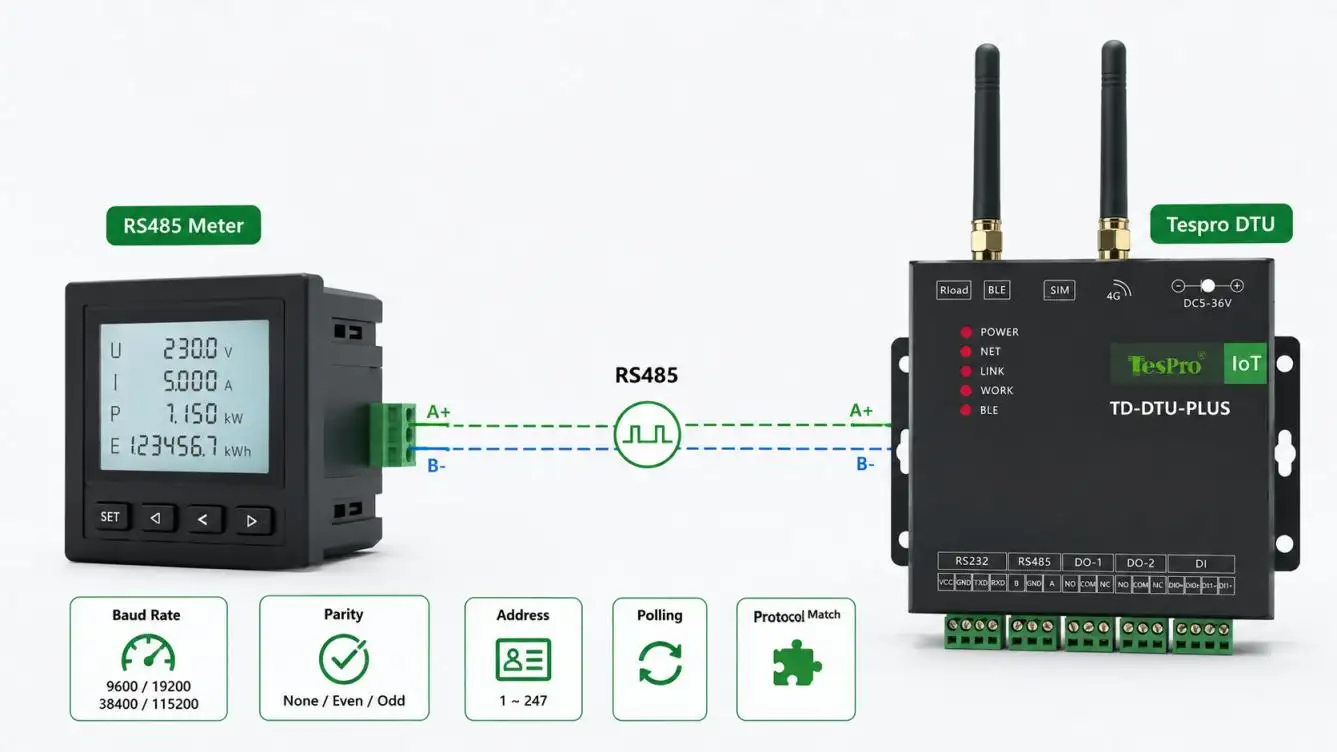

Remote meter reading becomes more demanding when RS485 electricity meters, water meters, flow meters, or other instruments are installed at sites without grid power, Ethernet, or permanent personnel. In these projects, selecting a DTU for Remote Data Transmission requires more than checking whether a device has RS485 and 4G interfaces.
A reliable architecture must align the complete data path:
RS485 Meter → DTU → 4G Network → Remote Server/Platform → Off-Grid Power System
For Tespro's TD-DTU series, project selection should therefore start with the meter interface, reporting interval, cellular network, power budget, and backend requirements—not with a long feature list.
Start With the RS485 Meter, Not the 4G Specification
RS485 defines the electrical interface, but it does not guarantee that two devices can exchange usable meter data.
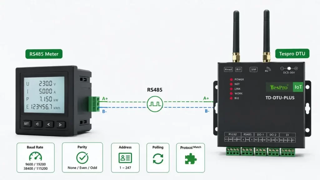
Before configuring a DTU for Remote Data Transmission, verify:
•Meter protocol, such as Modbus RTU or a manufacturer-specific protocol
•Baud rate
•Data bits and stop bits
•None, odd, or even parity
•Meter/slave address
•Register map or data definition
•Response timeout
•Number of meters sharing the RS485 bus
•Required polling interval
A common commissioning mistake is assuming that "RS485 compatible" means "protocol compatible." A DTU can receive serial bytes correctly while the remote application still fails to interpret the meter response.
Tespro TD-DTU products provide configurable serial communication for RS485 meter applications. The final serial settings should always be matched against the actual meter documentation before deployment.
Define What the DTU Does in the Data Chain
A typical DTU for Remote Data Transmission provides a communication bridge between serial field equipment and an IP-based cellular network.
Its basic role is:
- Receive data through RS485.
- Establish a 4G network connection.
- Transport data to a specified server or platform.
- Maintain or restore communication according to the configured operating mode.
This should not be confused with an industrial gateway.
Unless a specific TD-DTU configuration explicitly provides such functions, do not assume the DTU performs:
•Complex Modbus register mapping
•Multi-protocol conversion
•Edge computing
•Local AI analysis
•PLC logic
•Local process control
The key design question is therefore:
Where is the meter data parsed—the DTU or the remote application?
This distinction affects both device selection and platform integration.
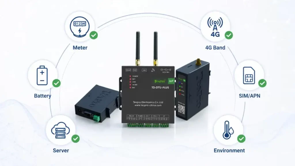
Match 4G Upload Method to the Remote Platform
A DTU being online does not mean the meter-reading system is working. The complete connection must be validated from serial input to application-level data.
| Integration Item | What Must Be Confirmed |
| LTE network | Operator and supported frequency bands |
| SIM | Public SIM, private APN, or project-specific configuration |
| Transport | TCP, UDP, MQTT, or supported application mode |
| Destination | Server IP address or domain |
| Port | Correct listening port and firewall access |
| Payload | Raw serial frame or structured data |
| Parsing | DTU side or server/platform side |
| Recovery | Reconnection and retransmission behavior |
Tespro's TD-DTU series includes cellular transmission options intended for serial-device communication. For projects using TCP, UDP, MQTT, or other supported modes, the server-side format and authentication requirements should still be confirmed before batch deployment.
Reporting Interval Directly Affects Off-Grid Power Design
For an off-grid DTU for Remote Data Transmission, reporting frequency is one of the most important engineering parameters.
A 1-minute reporting cycle creates a very different power profile from a 60-minute cycle.
| Reporting Interval | Data Resolution | Cellular Activity | Relative Power Demand | Typical Use |
| 1 minute | Very high | Very frequent | High | Fast operational monitoring |
| 5–15 minutes | High | Frequent | Medium-high | Utility or equipment monitoring |
| 30–60 minutes | Moderate | Lower | Medium-low | Routine remote meter reading |
| Several times/day | Low | Minimal | Low | Consumption records |
The correct interval should be based on how fresh the data actually needs to be, rather than automatically selecting the shortest possible interval.
Calculate Energy by Operating Cycle
Battery life should not be estimated from standby current alone.
A more realistic daily energy model is:
Daily Energy ≈ Standby + Meter Polling + Network Registration + Data Upload + Heartbeat + Retry Energy
Important variables include:
•Number of reports per day
•Number of RS485 meters
•Meter response time
•LTE registration duration
•Signal quality
•Upload payload size
•Retry count
•Operating temperature
•Battery aging
Poor LTE coverage can increase energy consumption because the modem may require longer registration periods or repeated transmission attempts.
For this reason, a low-power DTU for Remote Data Transmission should be evaluated using a defined reporting cycle and network condition, not only a nominal sleep-current figure.
Battery-Only or Solar + Battery?
"No external power" normally means no grid or mains supply, not that the DTU requires no electrical source.
Tespro's TD-DTU series includes configurations for conventional DC-powered installations as well as battery-supported remote applications. Where grid power is unavailable, the power system should be selected around required autonomy.
Battery-Only Deployment
More suitable when:
•Meter reports are infrequent
•Maintenance access is possible
•Required autonomy is predictable
•Solar installation is impractical
Solar + Battery Deployment
More suitable when:
•The site must operate unattended for long periods
•Reporting frequency is higher
•Seasonal energy requirements vary
•Battery replacement should be minimized
Battery sizing should also include temperature derating and sufficient margin for poor-signal retries.
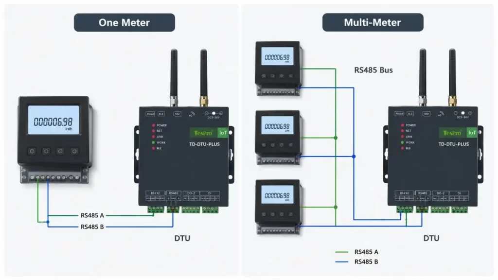
One Meter or Multiple RS485 Meters?
An RS485 bus may connect more than one meter, but increasing meter quantity changes the polling cycle.
For example:
More Meters → More Requests → Longer Polling Time → Longer Active Time → Higher Energy Consumption
Engineers should calculate the complete acquisition cycle using:
•Meter quantity
•Registers requested per meter
•Meter response latency
•Serial baud rate
•Timeout settings
•Retry policy
Do not specify the maximum number of meters from RS485 theory alone. The practical limit depends on wiring, protocol behavior, polling time, and the required reporting interval.
Installation Matters as Much as DTU Selection
A correctly specified DTU for Remote Data Transmission can still perform poorly if installation conditions are ignored.
RS485 Side
Check:
•A/B polarity
•Cable shielding and routing
•Bus topology
•Termination
•Ground potential
•EMI exposure
4G Side
Check:
•Antenna position
•Cable loss
•Actual operator coverage
•Signal quality inside the enclosure
•Metal cabinet shielding
Power Side
Check:
•Input voltage range
•Battery voltage under cellular transmit load
•Cable voltage drop
•Surge protection
•Low-temperature battery performance
Cellular transmission can create short periods of substantially higher current than standby operation. The power source must remain stable during these peaks.
Plan for Meter and Network Failures
Off-grid meter stations are often unattended, so recovery behavior should be verified before installation.
Ask whether the selected DTU for Remote Data Transmission provides the required:
•Meter communication timeout
•Automatic cellular reconnection
•Watchdog recovery
•Data buffering
•Store-and-forward transmission
•Retry limits
•Restart behavior after power loss
These capabilities should be confirmed for the actual TD-DTU model rather than assumed to be standard across every configuration.
Verify Compliance and Field Requirements
Before procurement, confirm the standards and documentation relevant to the destination market and application.
Typical checks include:
•RS485 electrical compatibility
•Meter protocol specification
•Cellular frequency bands
•Radio compliance
•EMC immunity and emissions
•ESD and surge test levels
•Operating temperature
•RoHS requirements
•Enclosure protection where applicable
For EU projects, the applicable radio configuration and conformity documentation should also be reviewed against Radio Equipment Directive requirements.
Select the DTU Around the Complete Metering System
The most suitable DTU for Remote Data Transmission is not necessarily the model with the largest number of functions. It is the configuration that correctly matches the meter, network, platform, power source, and reporting requirement.
Before requesting a Tespro TD-DTU configuration, prepare:
•Meter model and protocol
•RS485 parameters
•Register map
•Number of meters
•Polling interval
•Reporting interval
•Deployment country and operator
•SIM/APN requirements
•Server protocol, IP/domain, and port
•Power source and required autonomy
•Environmental conditions
Tespro's TD-DTU series is positioned for remote serial data transmission across applications such as RS485 meter reading and unattended cellular communication. By reviewing the RS485 interface, 4G connection, reporting cycle, backend requirements, and off-grid power budget together, Tespro can help buyers narrow the DTU for Remote Data Transmission configuration before field deployment.
FAQs
Q1. Can Tespro DTU be connected to an RS485 meter directly?
Tespro TD-DTU is a product line based on serial data transmission that includes RS485 connectivity in specific configurations. Before using a meter ensure the correct communication by checking the meter protocol, baud rate, parity, stop bits, address, and register definition.
Q2. Does Tespro DTU automatically convert Modbus RTU to MQTT or JSON?
Not typically. DTU for Remote Data Transmission should not be assumed to perform these kinds of protocol conversions. Some Tespro TD-DTU configurations support communication modes such as TCP, UDP, or MQTT, but the data handling method should be confirmed on the selected model and the server side architecture.
Q3. Can Tespro DTU be used to capture remote reading of electricity, water or flow meters?
Yes, this is a valid application of Tespro TD-DTU solutions when serial communication and cellular data transmission are available. The meter protocol and data format should be checked before the final configuration.
Q4. How does a Tespro DTU send RS485 meter data over 4G?
The DTU captures serial data from an RS485 device and transmits it to a remote server or platform using cellular data. The project should define the SIM, APN, server address, port, data transmission method, and expected data format.
Q5. Is it possible for a Tespro DTU to function in areas with no power grid?
Tespro has TD-DTU configurations for various power scenarios, including battery supported remote. For off-grid locations, battery size should be determined based on the report frequency, LTE signal quality, transmission duration, temperature and required standalone operation.